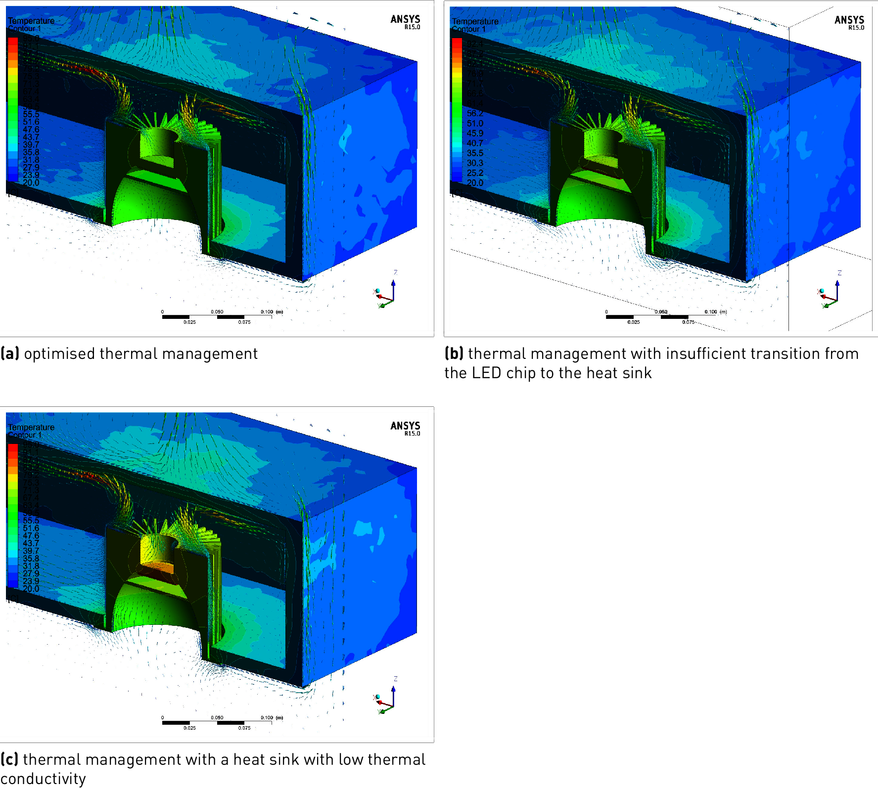
The graphics figure contain a false-colour image of the temperature distribution in a downlight in relation to the quality of the thermal management, determined via simulation. The images show the situation in a thermal equilibrium, meaning in permanent operation. The depicted temperature distributions can be explained as follows:
Example: Thermal management in a downlight

Figure 3.193: Comparative simulations of thermal management in a downlight in a thermal equilibrium, false-colour image.
In all three depictions, the downlight is in permanent operation with constant power consumption. The heat input is thus identical.
In a thermal equilibrium, heat input and heat release to the environment remain the same in all three cases.
Heat is released to the surrounding air via the surface of the cooling element. Here, (practically) the same temperature distribution appears for all three cases.
With optimised thermal management (figure a), the heat from inside the luminaire can be dissipated efficiently. The chip remains relatively cool. In the starting phase, the cooling element quickly heats up.
If the heat transfer from the chip to the cooling element is inefficient (figure b), a great difference in temperature must be present in order for heat to pass this barrier.
If the cooling element’s thermal conductivity is poor (figure c), heat transport through the volume to the surface is impeded. The cooling element is slower to heat up and heat is trapped.
In a thermal equilibrium (identical surface temperature, see above), the consequence is a continuous increase in temperature up to the heat source, meaning the LED chip.
The increased temperature at the LED chip in particular impacts the service life properties of the LED (see also chapter "Service life of LED products"). Luminous efficacy is also reduced (see also chapter "Luminous efficacy"). Specifications in the installation instructions must be observed.
Deviating operating positions can impair heat release to the surrounding air via convection. In case of downlights, the minimum dimensions for the mounting enclosure in particular must be observed.