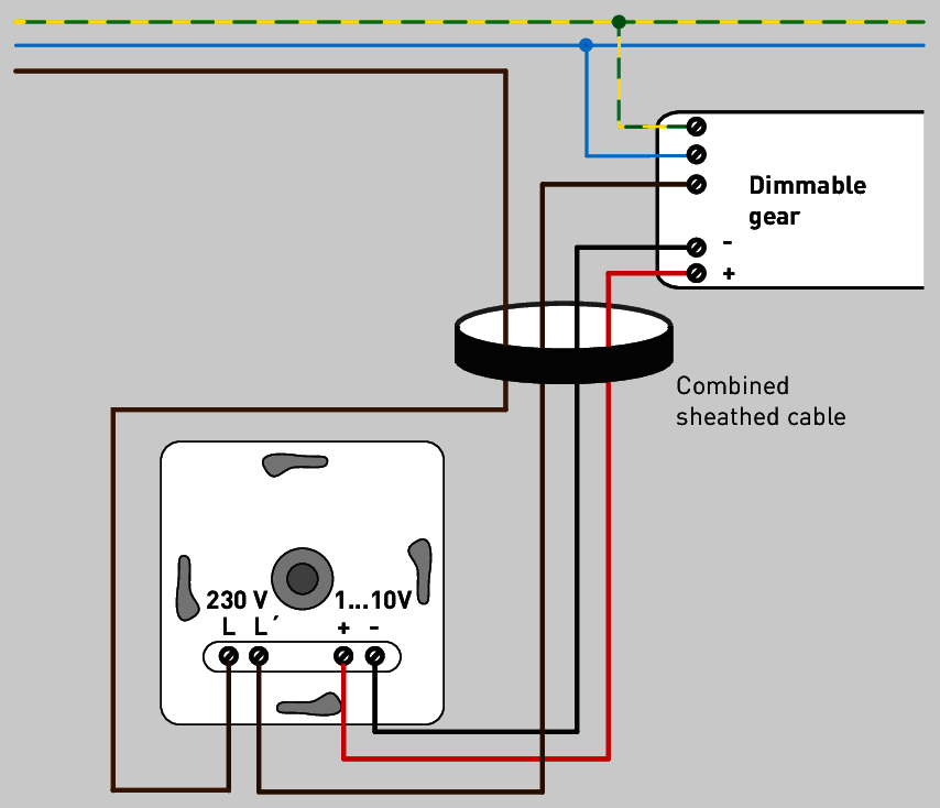
Figure 3.237: Schematic representation:
Rotary potentiometer as 1...10 V dimmer, e.g. for flush socket installation.
Postbox 1960
D-59753 Arnsberg

Figure 3.237: Schematic representation:
Rotary potentiometer as 1...10 V dimmer, e.g. for flush socket installation.
One interface that has been in use for technical lighting control gear for many years is the 1…10 V interface. It is not to be confused with the stage engineering interface (0…10 V).
Both require two additional wires to transmit the control signal in the form of a DC voltage. For the 1 ... 10 V interface - in contrast to the 0 ... 10 V interface - the operating device of the light source is the active component. This means:
The control gear unit provides the control power for the interface.
The open-circuit voltage of the opened interface is 10 V.
When the interface is opened, the control gear unit is in 100% operation, meaning at maximum lamp power.
The control voltage can be influenced using an electronic resistor (potentiometer) as a dimmer.
Below a control voltage of 1 V, the control gear unit is in minimum operation.
Control power for short-circuited interfaces is not standardised but limited to a maximum of 1 mA.
To ensure correct functioning of the interface, it is important to make sure that the connected potentiometer is not overcharged by the control power of the control gear units to be operated.
In conclusion, this is an analogue signal. It is characterised by permanent signal availability/presence in the form of control voltage. There is no standardised curve to depict the ratio of present control voltage and luminous flux generated by the light source for the 1…10 V interface.
In contrast to the aforementioned passive 0…10 V interface used predominantly in stage lighting, the 1…10 V interface is a pure dimming interface. The control gear unit is not switched via the control signal. To switch the lighting on/off, it is therefore always necessary to switch the supply voltage (see figure).
The control signal is based on low voltage; however, it is not a safety extra-low voltage within the installation. The control line must therefore be installed in a in a mains voltage-stable manner. Installation in a joint sheathed cable with the mains voltage line is permissible.